BOM
BOM
 My Request
How to Verify a Pin-to-Pin Replacement IC Before PCB Assembly
Contents
- Start With the Package and Pinout
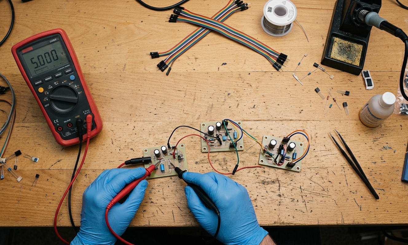
- Use the Multimeter for a Static Comparison
- Why One Strange Reading Does Not Automatically Mean the IC Is Bad
- Check for Shorts Before Applying Power
- Dynamic Voltage Testing Comes After Static Checks
- Do Not Compare Output Voltage With No Load Alone
- What About Resistance and Diode Results That Do Not Match?
- A Better Way to Qualify a Drop-In Alternative
- My View on Second-Source Testing
Finding a second source is easy. Approving it for production is not.
A supplier may offer an IC with the same package, similar specifications, and a lower price. The real question is whether it will behave correctly on the existing PCB.
Apin-to-pin replacement ICshould be checked in two stages: physical compatibility and electrical compatibility.
A digital multimeter is useful for the second stage, especially as an early screening tool. It is not a substitute for a complete functional or reliability test.
Start With the Package and Pinout
Before connecting power, check the datasheets.
The package name alone is not enough. Two devices may both be SOT-23, SOIC-8, or SOT-223 and still have different pin assignments.
I normally compare:
· Pin number and function
· Package dimensions
· PCB footprint
· Exposed pad or thermal tab
· Input and output polarity
· NC pins
This is particularly important when checking aLDO alternative pinout.
Take AMS1117-3.3 and TITLV75533PDBVRas an example. AMS1117-3.3 is commonly supplied in SOT-223, while TLV75533PDBVR is a 5-pin SOT-23 device with IN, OUT, GND, EN and NC pins. TI also specifies a 1.45V to 5.5V input range and 500mA output capability for the TLV755P.
So TLV75533PDBVR is not a direct physical replacement for an AMS1117-3.3 on an unchanged PCB. It is a redesign option.
That distinction should be made before any electrical testing.
Use the Multimeter for a Static Comparison
Once the physical differences are understood, the multimeter can help withsecond source IC testing.
Do not test an IC on a powered board using resistance or diode mode. Remove power, discharge capacitors, and make sure external circuits will not affect the reading.
For some ICs, diode mode can reveal internal protection structures between functional pins, VCC, and GND.
The useful part is the comparison.
If five known-good samples show similar readings and a proposed replacement shows a very different pattern, that is worth investigating.
I would record the measurements rather than relying on memory:
|
Test |
Known-Good Part |
Replacement |
What It Tells You |
|
Pin → GND |
Record reading |
Record reading |
Static conduction pattern |
|
Pin → VCC |
Record reading |
Record reading |
Protection structure comparison |
|
Pin → Pin |
Record reading |
Record reading |
Possible unexpected conduction |
|
GND → VCC |
Record reading |
Record reading |
Obvious short or leakage |
|
NC → GND/VCC |
Record reading |
Record reading |
Check against datasheet |
This ismultimeter diode drop comparison, not a final pass/fail test.
There is no universal diode voltage that proves an IC is genuine or electrically equivalent. Internal circuits vary between device families.
Why One Strange Reading Does Not Automatically Mean the IC Is Bad
This is where a lot of component testing goes wrong.
An IC contains more than simple PN junctions. Input protection, bias circuits, MOS structures, and internal resistors can all affect a static measurement.
Probe contact and meter current can also change the result.
For that reason, I would be suspicious of a replacement only when the whole measurement pattern is different from a known-good part, not because one number is 50mV higher or lower.
The same rule applies tocross reference component validation.
A cross-reference database is useful for finding candidates. It does not prove that two devices behave identically.
Check for Shorts Before Applying Power
Before the first powered test, I make one more static check.
Measure the main supply path for an obvious short and compare it with the original device.
This is particularly useful for power ICs and LDOs.
The test is simple:
VCC → GND
A very low resistance reading can be a warning sign, although the exact value depends on the internal circuitry.
Again, do not judge the part from resistance alone. The surrounding circuit can create a low reading.
A safer approach is to test the replacement on a small fixture or evaluation board before putting it into a production PCB.
Dynamic Voltage Testing Comes After Static Checks
If the static measurements look reasonable, the next step is controlled power-up.
This is where a bench supply is preferable to powering an expensive production board directly.
Set the supply to the correct voltage and use a current limit.
Then measure the important nodes in VDC mode:
· Input voltage
· Output voltage
· Enable voltage
· Reference or feedback node
· Shutdown state
For TLV75533PDBVR, for example, TI specifies an EN input and a 3.3V output version with a maximum dropout of 238mV at 500mA. The device also requires suitable input and output capacitance; TI specifies at least 1µF effective capacitance at the pins.
That means a multimeter can confirm whether the basic supply and enable conditions are present, but it cannot tell you whether the LDO is stable under load.
That requires a proper load test and, where necessary, an oscilloscope.
Do Not Compare Output Voltage With No Load Alone
A replacement LDO can show 3.3V on a multimeter and still fail during load changes.
This is why I would not approve anLDO alternative pinout checkfrom a no-load voltage measurement.
Add an appropriate load and measure the output again.
Then increase the load toward the expected operating current and watch the voltage.
For TLV755P, TI specifies 500mA maximum output current and a 25µA typical quiescent current. Those are datasheet conditions, not a statement that every PCB will deliver 500mA under all temperatures.
What About Resistance and Diode Results That Do Not Match?
That is not necessarily a failure.
Some replacement ICs use different internal protection circuits while remaining functionally suitable.
The opposite is also true: two ICs can show similar multimeter readings while having different timing, thermal, noise, or load characteristics.
So the multimeter is most useful for finding obvious problems:
short circuit, unexpected conduction, wrong pin behavior, or a replacement with a clearly different static signature.
It is not an instrument for proving complete equivalence.
A Better Way to Qualify a Drop-In Alternative
For a production replacement, I would use a short sequence:
Step 1:Verify package and pinout.
Step 2:Compare the important electrical specifications.
Step 3:Perform static resistance and diode checks.
Step 4:Power the part on a controlled test fixture.
Step 5:Check output voltage and key logic levels under load.
Step 6:Test temperature, startup, load changes, and other application-specific conditions.
Only after these checks would I consider changing the production BOM.
This is especially important for adrop-in alternative verificationproject. A part that passes the first three steps is only a candidate.
My View on Second-Source Testing
I would not describe a replacement as "qualified" because it passed a multimeter test.
The meter is useful because it is cheap, fast, and good at finding obvious electrical differences before an expensive PCB assembly run.
But the final decision should be based on the application.
A MOSFET needs switching and thermal testing.
An LDO needs load and stability testing.
A logic IC may need timing verification.
An optocoupler may need CTR testing.
The test method should follow the component.
Forsecond source IC testing, I prefer a simple rule: use the multimeter to eliminate bad candidates early, then use a controlled bench test to confirm the parts that remain.
That takes a little more time before production, but it is much cheaper than discovering an incompatibility after thousands of PCBs have already been assembled.