BOM
 My Request
Ultra-Low Quiescent Current LDOs vs. Synchronous Buck Regulators in Battery-Powered IoT Nodes
Contents
- Key Takeaways
- 1. Why Quiescent Current Matters More Than Many Designers Expect
- 2. Ultra-Low Iq LDOs: A Good Fit for Sleep-Dominated Devices
- 3. Synchronous Buck Regulators: Better for Higher Current Loads
- 4. LDO vs. Buck: Which One Gives Better Battery Life?
- 5. Why Many IoT Nodes Use Both an LDO and a Buck Converter
- 6. Can Switching Noise Affect Precision Sensor Measurements?
- 7. A Practical Power Management IC Selection Checklist
- Conclusion
A battery-powered sensor can work perfectly on the test bench and still run out of battery much earlier than expected in the field.
The problem is not always the microcontroller or wireless radio. Sometimes, the power supply consumes more energy than the designer expected, especially when the device spends most of its time waiting for the next measurement or transmission.
This is where the choice between an ultra-low quiescent current (Iq) low-dropout regulator (LDO) and a synchronous buck regulator becomes important.
Both devices regulate voltage, but they behave differently under light loads, during active operation and when the input voltage is close to the required output voltage. For IoT sensors, wearable electronics and wireless monitoring nodes, understanding these differences can make a measurable difference to battery life.
Key Takeaways
An ultra-low Iq LDO is often a good choice for low-power circuits that spend long periods in sleep mode. It requires few external components, introduces no switching ripple of its own and can consume very little current when properly selected.
A synchronous buck regulator is usually more attractive when the input voltage is significantly higher than the output voltage or when the load requires substantial current. It can achieve high conversion efficiency, particularly during active operation, but its switching losses, light-load behavior and external components must be considered.
For many battery-powered IoT designs, using both regulators can be more effective than relying on either one alone. The right arrangement depends on the battery voltage, load profile, standby current, noise requirements and total power budget.
1. Why Quiescent Current Matters More Than Many Designers Expect
Quiescent current is the current a regulator consumes to operate its internal control circuitry. It is not the same as the current delivered to the load.
For an IoT node that measures temperature every few minutes and transmits data occasionally, the active operating time may be very short compared with the total time spent in standby.
During these long idle periods, even a small continuous current can gradually drain the battery.
Consider a regulator with a quiescent current of 1 µA. Over one year, its own current consumption amounts to approximately 8.76 mAh, assuming the current remains constant.
That may sound insignificant, but a complete device can contain several always-on circuits, including voltage monitors, sensors, memory and wireless wake-up circuitry. Their combined standby consumption can become a major part of the energy budget.
This is why selecting an ultra-low Iq LDO for coin cell batteries requires more than checking the headline current figure. Engineers also need to account for battery self-discharge, regulator shutdown current, output loading and the current consumed by the rest of the circuit.
One practical point is often overlooked: a regulator advertised with nanoamp-level quiescent current may not maintain that figure across every input voltage, output voltage and operating condition. The electrical characteristics table and test conditions matter more than the product headline.
2. Ultra-Low Iq LDOs: A Good Fit for Sleep-Dominated Devices
An LDO regulates its output by controlling a series pass element. Because it does not rely on an inductor or a switching cycle, its circuit is generally straightforward.
This makes it useful for powering microcontrollers, low-power sensors, real-time clocks and other circuits that require a stable supply during long sleep periods.
Its main advantages include:
Very low quiescent current in suitable device families.
Low output noise compared with many switching regulators.
Few external components and a compact PCB layout.
No switching-frequency ripple generated by the regulator itself.
The last point is especially useful in sensitive analog circuits. A precision sensor measuring small voltage changes may be easier to design when its supply does not introduce switching harmonics.
However, an LDO is not automatically the most efficient option.
Its approximate efficiency is:
Efficiency ≈ Vout / Vin × 100%
This approximation assumes that the input and output currents are nearly equal and ignores the regulator's own operating current.
For example, if an LDO converts 5 V to 3.3 V, its idealized efficiency is about 66%. The remaining input power is largely dissipated as heat in the pass element and other internal losses.
If the input is 3.6 V and the output is 3.3 V, the idealized efficiency rises to about 92%, provided the LDO has sufficient headroom to maintain regulation.
The difference is substantial. When the input-to-output voltage gap is large, a buck regulator may be a better choice for loads that draw meaningful current.
Engineers should also check dropout voltage, maximum output current, load-transient response, output-capacitor requirements and stability conditions before selecting an LDO.
3. Synchronous Buck Regulators: Better for Higher Current Loads
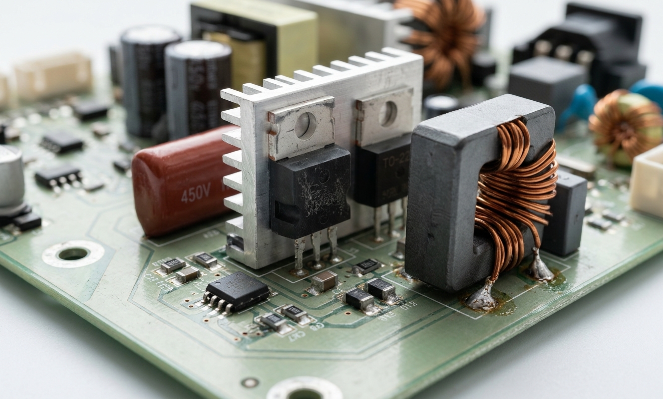
A synchronous buck regulator converts a higher DC voltage into a lower one using controlled switching. It typically uses two MOSFET switches and an external inductor to transfer energy efficiently to the load.
Unlike an LDO, it does not need to dissipate the entire voltage difference as heat. This makes it particularly useful when a battery-powered device needs a lower voltage rail at moderate or high current.
For example, a wireless monitoring node may draw only a few microamps while sleeping but require tens or hundreds of milliamps during radio transmission.
A well-designed synchronous buck converter can deliver high efficiency during these active periods. Efficiencies above 90% are achievable in suitable operating conditions, although actual performance depends on the input voltage, output voltage, load current, switching frequency and component selection.
The trade-offs are equally important.
A buck regulator requires an inductor and usually input and output capacitors. Its switching action generates ripple and electromagnetic interference that must be managed through component selection, PCB layout and filtering.
Its performance at very light loads also varies by device. Pulse-skipping or burst-mode operation can improve efficiency, but may change output ripple characteristics. Some regulators draw enough internal current that they are not ideal for applications dominated by extremely long sleep periods.
For this reason, a high-efficiency buck converter should not be selected solely because its datasheet reports 95% efficiency at a particular load.
The more useful question is how efficiently it operates across the device's actual duty cycle.
4. LDO vs. Buck: Which One Gives Better Battery Life?
There is no universal winner. The answer depends on how the device operates.
|
Selection Factor |
Ultra-Low Iq LDO |
Synchronous Buck Regulator |
|
Sleep-mode operation |
Often excellent when Iq is very low |
Depends on standby current and light-load mode |
|
High-current bursts |
Simple, but may dissipate significant power |
Often more efficient |
|
Input-output voltage difference |
Efficiency falls as voltage difference increases |
Usually better suited to substantial step-down conversion |
|
Output noise |
No switching ripple generated internally |
Switching ripple and harmonics require consideration |
|
External components |
Few; no inductor |
Inductor and capacitors required |
|
PCB design |
Generally simpler |
Requires careful switching-current loop layout |
|
Typical applications |
Low-power sensors, RTCs, always-on MCU rails |
Radio bursts, processor rails, higher-current loads |
A useful way to compare the two is to calculate the energy consumed during a complete operating cycle.
Suppose a sensor spends 99% of its time asleep and only 1% transmitting data. An LDO with exceptionally low standby current may perform well because the regulator spends most of its life in the sleep state.
A buck regulator may be more efficient during transmission, but its standby losses could offset some of that advantage.
Now consider a device that performs frequent wireless transmissions or continuously processes sensor data. The active period becomes more important, and the buck converter's higher conversion efficiency may dominate the result.
For battery life optimization in wearable electronics, engineers should compare average battery current over a representative operating cycle rather than efficiency at one selected load point.
5. Why Many IoT Nodes Use Both an LDO and a Buck Converter
A mixed power architecture can be useful when one regulator cannot satisfy both standby and active operating requirements.
Consider a battery-powered environmental monitor with a wireless radio, microcontroller and precision analog sensor.
The buck regulator can provide an efficient supply for the radio or other loads that draw high current during active operation. An ultra-low Iq LDO can supply a sensitive analog rail or an always-on circuit that benefits from low noise and low standby consumption.
However, the architecture must be designed carefully.
If the LDO is placed after the buck converter, the LDO's input voltage must remain high enough above its output voltage to maintain regulation. The added regulator also introduces its own quiescent current and dropout losses.
In some designs, a single buck regulator is sufficient. In others, an LDO supplied directly from the battery may be more appropriate, provided the battery voltage remains within the LDO's operating range.
The goal is not to use two regulators simply because each has an attractive specification. It is to assign each power rail to the regulator that best matches its load profile.
6. Can Switching Noise Affect Precision Sensor Measurements?
Yes. This is one of the main reasons engineers sometimes choose an LDO for analog sensor circuits even when a buck converter would be more efficient.
Switching regulators produce periodic voltage and current waveforms. Their harmonics can couple into sensitive signal paths through the supply rail, ground impedance, PCB parasitic coupling or electromagnetic radiation.
The resulting interference may affect low-level measurements, particularly in circuits using high-gain amplifiers, precision ADCs or sensors with small output signals.
A low-noise LDO can help attenuate supply disturbances when its power-supply rejection is adequate at the relevant frequency. But an LDO cannot correct every layout or grounding problem.
Ferrite beads and local bypass capacitors can help isolate sensitive rails in some designs. They must be selected with attention to DC resistance, current rating, impedance versus frequency and possible interaction with the connected capacitors.
Other useful measures include keeping switching-current loops compact, separating sensitive analog routing from noisy switching nodes and providing appropriate ground-return paths.
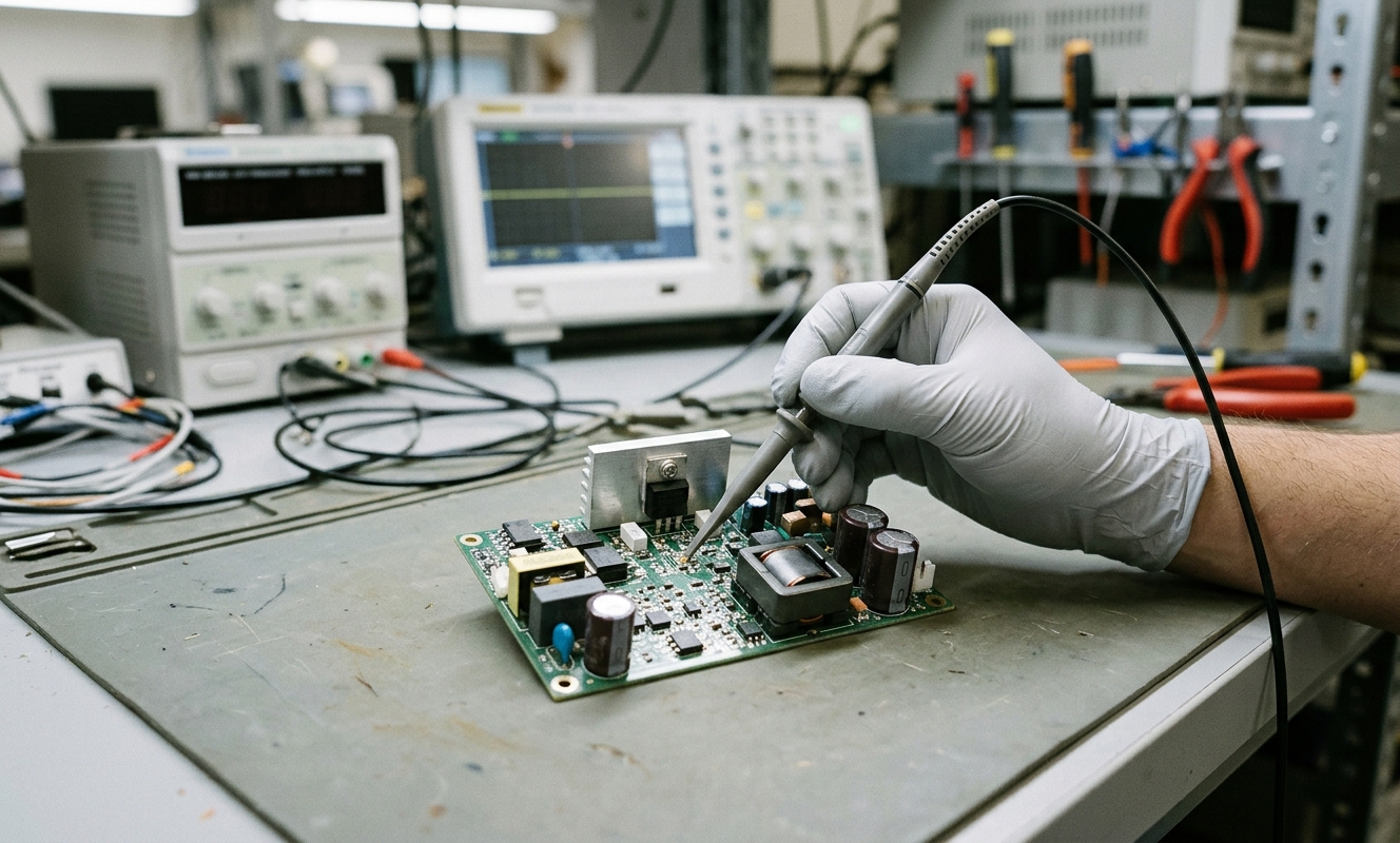
For the lowest-noise measurements, engineers should test the complete circuit under realistic switching and load conditions instead of relying only on the regulator's noise specification.
7. A Practical Power Management IC Selection Checklist
Before choosing a replacement or approving a new power management IC, I would check the following parameters.
|
Parameter |
What to Check |
|
Quiescent current |
Typical and maximum values under relevant conditions |
|
Shutdown current |
Battery drain when the regulator is disabled |
|
Input voltage |
Full battery operating range, including fresh and depleted states |
|
Output voltage |
Accuracy, tolerance and transient behavior |
|
Load current |
Sleep current, average current and peak demand |
|
Conversion efficiency |
Efficiency across the actual load profile |
|
Dropout voltage |
Whether an LDO maintains regulation near battery depletion |
|
Output ripple and noise |
Suitability for analog and RF-sensitive circuits |
|
External components |
Inductor, capacitor, ESR and layout requirements |
|
Package and thermal limits |
Footprint, current capability and operating temperature |
|
Lifecycle and sourcing |
Exact MPN, availability and long-term supply continuity |
For component procurement, the full manufacturer part number should be included in the RFQ. Two regulators with the same output voltage can have very different quiescent currents, pin assignments, enable behavior and external-component requirements.
A replacement should therefore be evaluated against the actual circuit conditions, not just the nominal voltage and package.
Conclusion
Ultra-low Iq LDOs and synchronous buck regulators solve different power-management problems.
An LDO is often a strong choice for circuits that spend long periods in sleep mode or require a quiet supply for sensitive analog measurements. A synchronous buck regulator is usually more suitable when the design needs efficient voltage conversion during higher-current operation.
For battery-powered IoT nodes, the best solution depends on the complete load profile. Sleep current, active current, input voltage, regulator efficiency and noise requirements all contribute to the final battery life.
In many designs, combining a low-Iq LDO with a buck converter can provide a useful balance between standby consumption and active efficiency. In others, a single carefully selected regulator is the simpler and more effective option.
The practical recommendation is to measure the device's average battery current across a realistic operating cycle, verify the regulator's datasheet conditions and choose the exact MPN that meets both the electrical requirements and the product's long-term sourcing needs.