BOM
BOM
 My Request
PCB Thermal Diagnostics and Hardware Troubleshooting: Test Equipment in QA/QC
Contents
- Key Takeaways
- 1. Why a Hotspot Is Only the Beginning
- 2. A Practical Non-Contact PCB Thermal Hotspot Detection Guide
- 3. What Is the Thermal Camera Resolution Requirement for SMD Inspection?
- 4. Where an Industrial Process Calibrator Fits In
- 5. Benchtop vs Portable Test Tools for Electronics QA
- 6. A Better QA/QC Question: "Where Did the Fault Start?"
- Conclusion
A PCB can pass an electrical test and still have a thermal problem.
A MOSFET may be running hotter than expected. A power IC may have poor heat transfer to the PCB. A connector can develop unusual resistance and turn into a local hotspot. Sometimes the component itself is fine, but the solder joint, copper area, thermal via pattern, or surrounding layout is not.
This is whyPCB thermal diagnosticsdeserves a place in quality assurance and quality control, especially when a product is already in pilot production or field service.
Key Takeaways
Thermal imaging provides a fast, non-contact way to find abnormal heat patterns on an operating PCB, but temperature readings must be interpreted carefully because surface emissivity affects measurement accuracy.
For industrial systems, a process calibrator can also be used to source, measure, and simulate electrical, temperature, and pressure signals, helping engineers separate a sensor or transmitter problem from a control-system problem.
In practice, the useful workflow is not "scan everything with a thermal camera." It is to compare known-good and suspect boards under similar load, then verify the related electrical or sensing path with the right test instrument.
1. Why a Hotspot Is Only the Beginning
The first mistake in PCB troubleshooting is treating a hot component as the root cause.
Imagine two boards using the same power device. One runs at a normal temperature while the other shows a much hotter area around the same package. That difference is useful, but it does not immediately tell you why the board is failing.
The possible causes may include:
· Excessive current
· Higher-than-expected resistance
· A damaged component
· Poor soldering
· Insufficient copper area
· Blocked or poorly designed thermal paths
· A nearby component causing abnormal loading
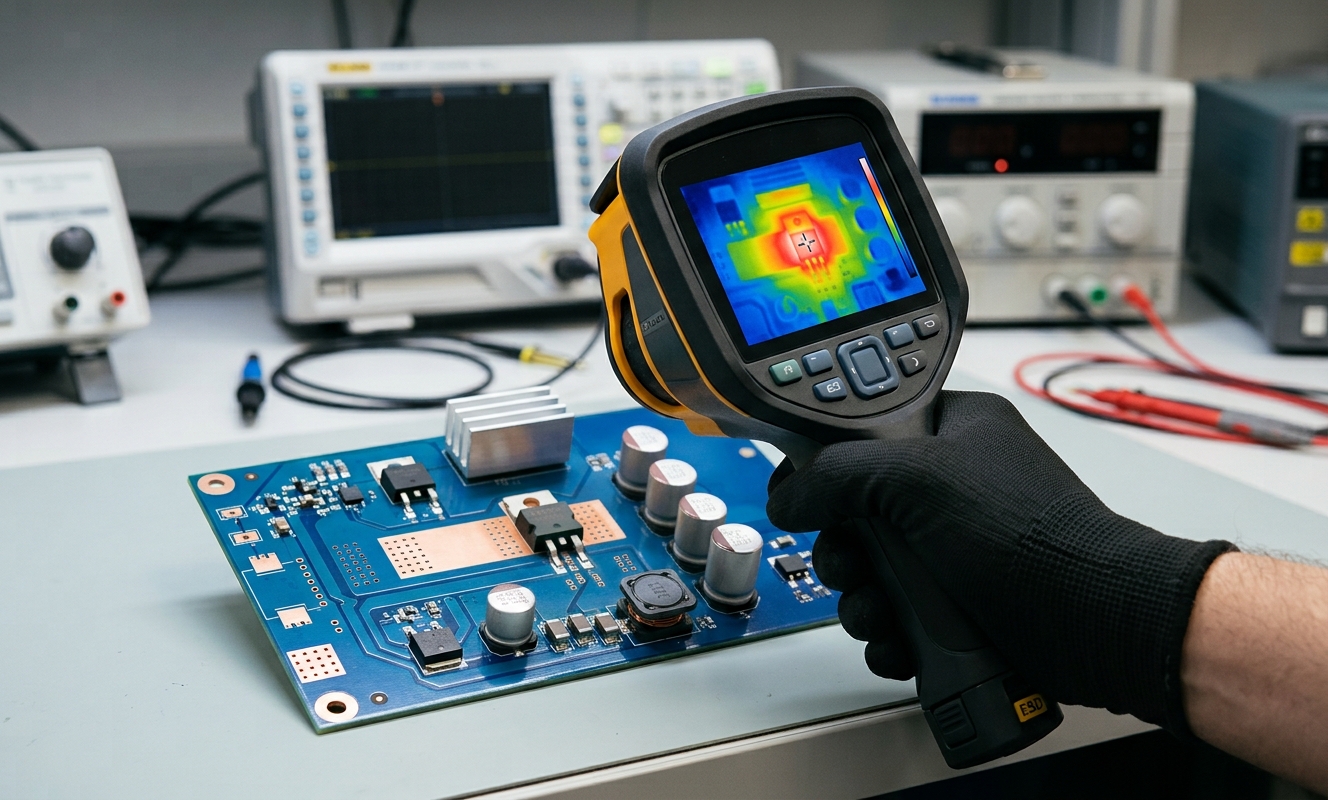
A thermal camera is valuable because it shows thepatternof heat. Instead of measuring one point after another with a probe, an engineer can quickly see where the board behaves differently.
Fluke has documented a PCB troubleshooting case in which thermal imaging was used to distinguish faulty motor-driver boards from known-good boards. The reported surface temperatures were dramatically different under comparable conditions, helping the team isolate the problem before returning to the component supplier.
That is an important QA/QC lesson:thermal imaging is often most useful as a comparison tool, not simply as a temperature gun.
2. A Practical Non-Contact PCB Thermal Hotspot Detection Guide
A good inspection starts before the camera is switched on.
Run a known-good PCB under a defined operating condition first. Record the load, input voltage, operating time, ambient condition, and major heat sources.
Then test the suspect board under the same conditions.
Look for differences such as:
|
Inspection Item |
What to Compare |
Possible Problem Area |
|
Power IC |
Surface temperature and heat pattern |
IC loading or thermal path |
|
MOSFET |
Drain/source region and surrounding PCB |
Conduction loss or switching stress |
|
Diode |
Package temperature and copper area |
Forward loss or abnormal current |
|
Connector |
Temperature across terminals |
Contact resistance |
|
Inductor |
Coil and core temperature |
Saturation or excessive current |
|
Sensor section |
Local temperature stability |
Sensor or surrounding circuitry |
There is another important point:not every shiny component surface gives a reliable absolute temperature measurement.
Low-emissivity metal surfaces can make infrared measurements difficult. Fluke specifically notes that emissivity can affect electrical equipment temperature measurements and recommends qualitative comparisons when precise quantitative measurements are difficult to establish.
So my view is simple: use the thermal image to find the suspicious area first, then confirm the electrical cause with other instruments.
3. What Is the Thermal Camera Resolution Requirement for SMD Inspection?
This question comes up often:
Do you need an expensive high-resolution thermal camera to inspect a PCB?
Not always.
The real issue is spatial resolution, working distance, optics, focus, and the physical size of the target. A small SMD package can occupy only a few pixels in a poor thermal image.
Fluke explains that image quality depends on focus, optics, spatial resolution, pixels, and field of view. It also notes that an out-of-focus image can seriously affect the usefulness of temperature measurements.
For example, Fluke's TC03A Pro mobile thermal camera is specified with a 384 × 288 infrared sensor and 1.14 mrad spatial resolution, and the manufacturer specifically describes PCB hotspot inspection as one of its applications.
This leads to a better purchasing question:
How large is the smallest component I need to inspect, and from what distance?
That question is more useful than simply asking whether a camera has "high resolution."
4. Where an Industrial Process Calibrator Fits In
At first glance, anindustrial process calibratorseems unrelated to PCB thermal troubleshooting.
In industrial electronics, however, the two problems can meet.
A control board may receive a 4–20 mA signal from a transmitter. A temperature sensor may report an abnormal value. The PCB looks normal under thermal inspection, but the system still fails.
This is where a process calibrator can help isolate the fault.
For example, the Fluke 725 can measure and source mA, voltage, temperature, frequency, resistance, and pressure with optional pressure modules. It can also perform transmitter calibration and provide loop power while measuring mA.
The Fluke 754 adds documenting functions and HART communication for supported industrial instrumentation workflows.
So the testing chain can become:
PCB thermal inspection → electrical verification → sensor/transmitter simulation → system-level confirmation
This is much more useful than replacing a suspicious sensor immediately.
5. Benchtop vs Portable Test Tools for Electronics QA
Another practical question is:
Should QA teams use benchtop instruments or portable test tools?
My answer is that the choice should follow the failure stage.
A benchtop setup makes sense when engineers repeatedly test the same board in a controlled environment. Portable tools become more useful when the problem must be checked on a production line, test station, machine, or industrial plant.
That distinction is especially relevant to anindustrial test equipment supplierserving both electronics manufacturers and maintenance teams.
For PCB development, repeatability matters. For field troubleshooting, speed and portability often matter more.
A useful equipment set may therefore combine:
|
QA/QC Task |
Suitable Test Approach |
|
Find abnormal PCB heat |
Thermal camera |
|
Check voltage/current |
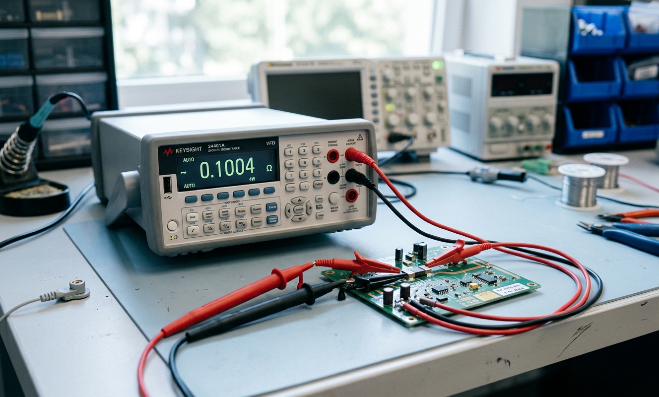
Digital multimeter |
|
Verify signal behavior |
Electronic test equipment |
|
Validate process sensors |
Process calibrator |
|
Confirm pressure/temperature loop |
Process calibration equipment |
|
Compare good vs failed boards |
Repeatable thermal + electrical test |
6. A Better QA/QC Question: "Where Did the Fault Start?"
This is probably the most useful question in hardware troubleshooting.
A failed board does not always fail because of the component that gets hottest. The hotspot may only be the final visible symptom.
A supplier may receive an RFQ for a replacement MOSFET, power IC, thermistor, or sensor. Before changing the part, the engineering team should ask whether the surrounding circuit is creating the stress.
Was the original component incorrectly selected?
Is the PCB thermal path adequate?
Is the sensing signal wrong?
Is a connector generating resistance?
Is the problem limited to one production lot?
These questions are wherethermal diagnostics, electrical measurement, and process calibrationbecome more valuable than simply swapping components.
For buyers and maintenance teams, this also changes how test equipment should be sourced. The best tool is not necessarily the one with the longest specification sheet. It is the one that can answer the specific failure question with repeatable data.
Conclusion
PCB thermal inspection is most effective when it is part of a broader troubleshooting workflow.
A thermal camera can quickly reveal abnormal heat distribution. Electrical instruments can confirm current, voltage, or resistance problems. An industrial process calibrator can help verify sensors, transmitters, loops, and process signals outside the PCB itself.
For QA/QC teams, the goal should not be to collect more test data simply for documentation. The goal is to connect the data and find the actual failure path.
For electronics manufacturers, maintenance departments, and buyers looking for anindustrial test equipment supplier, this approach also creates a practical bridge between test equipment and component sourcing. A thermal hotspot may eventually lead to the need for a different MOSFET, regulator, sensor, connector, or other electronic component-but that replacement decision should come after the failure mechanism is understood.
That is where testing stops being a final inspection step and becomes part of engineering diagnosis.