BOM
BOM
 My Request
IRFZ44N Replacement Guide: IRF3205 and TO-252 DPAK MOSFET Cross-Reference
Contents
- IRFZ44N vs IRF3205 vs DPAK
- Is Lower RDS(on) Always Better?
- Why Gate Charge Can Affect EMI
- TO-220 vs TO-252: What Happens to Thermal Design?
- Can TO-220 Be Replaced by DPAK Without Changing the PCB?
- When Does a DPAK Part Make Sense?
- What Should Be Checked Before Approving a Second Source?
- My View on IRFZ44N Replacement
- Need Help Finding a Power MOSFET Alternative?
IRFZ44N is still found in older motor controllers, power supplies, inverters, and other high-current boards. It is a 55V N-channel MOSFET in a TO-220 package. IRF3205 is also a 55V TO-220 device, but its lower RDS(on) comes with a much higher gate charge.
That difference is more useful than simply asking which part has the higher current rating.
When looking for anIRFZ44N replacement, I normally check the device in this order: voltage margin, RDS(on) at the real gate voltage, gate charge, thermal path, then package.
IRFZ44N vs IRF3205 vs DPAK
|
Part |
VDS |
ID @ 25°C |
RDS(on) Max |
Qg Typ. @ 10V |
RθJC Max |
Package |
|
IRFZ44NPBF |
55V |
49A |
17.5mΩ |
42nC |
1.8K/W |
TO-220 |
|
IRF3205PBF |
55V |
110A |
8mΩ |
97.3nC |
1.0K/W |
TO-220 |
|
IRFR1205TRPBF |
55V |
44A |
27mΩ |
43.3nC |
1.8K/W |
DPAK / TO-252 |
These are datasheet figures under specified test conditions. The listed drain current is not a promise that the MOSFET can carry that current continuously on any PCB.
Is Lower RDS(on) Always Better?
Not in a switching circuit.
Conduction loss is easy to estimate:
P = I² × RDS(on)
At 20A, 17.5mΩ gives about 7W, while 8mΩ gives about 3.2W, assuming the resistance values apply at the actual operating temperature and gate voltage.
That makes IRF3205 attractive for high-current applications.
But its typical total gate charge is 97.3nC, compared with 42nC for IRFZ44N. A gate driver has to move that charge every switching cycle. At higher frequency, the extra charge can increase driver loss and switching losses.
So when comparing anIRF3205 drop in alternative, I would not look at the 8mΩ number alone.
Why Gate Charge Can Affect EMI
This part is often missed in replacement work.
A lower-Qg MOSFET can switch faster when driven by the same gate circuit. Faster switching means a steeper drain-voltage transition, or higherdV/dt. Depending on the layout, parasitic capacitances, gate resistance, and the rest of the circuit, that can increase ringing, conducted noise, or radiated EMI. Infineon also notes that rapid VDS transitions can couple through parasitic capacitance and cause unwanted MOSFET turn-on.
Does that mean a low-Qg MOSFET is a bad choice?
No.
It means the gate network may need to be reviewed after the substitution. A small change in gate resistance can sometimes give a better compromise between switching loss and EMI than simply choosing the lowest-Qg device available.
For a motor driver or switching power supply, I would check the switching waveform after changing the MOSFET, especially around the Miller plateau.
TO-220 vs TO-252: What Happens to Thermal Design?
This is where the package change becomes important.
TheIRFZ44NPBFandIRF3205PBFuse TO-220. Their cases are designed for mounting to an external heat sink when required. Infineon specifies a maximum junction-to-case thermal resistance of 1.8K/W for IRFZ44N and 1.0K/W for IRF3205.
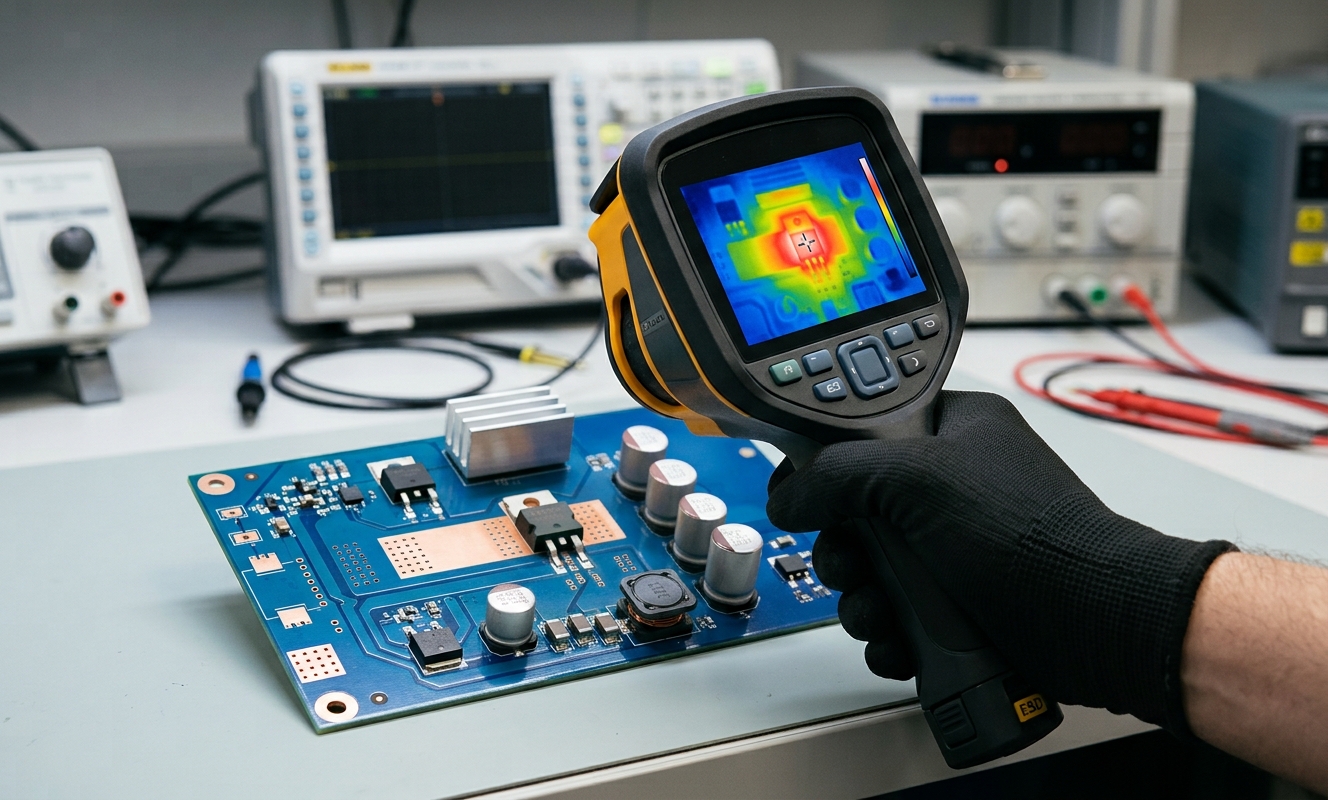
TheIRFR1205TRPBFuses DPAK/TO-252 and has a specified RθJC of 1.8K/W. Its thermal path relies much more heavily on the PCB copper area beneath and around the device.
This brings up an important point aboutDPAK vs TO-220 thermal resistance:
RθJC is not the same thing as actual junction temperature on the finished PCB.
A TO-220 mounted to a good heat sink may outperform a DPAK on a small copper area. A DPAK with large copper regions and multiple PCB layers can also remove substantial heat.
The package datasheet gives you one part of the thermal path. The PCB determines much of the rest.
Can TO-220 Be Replaced by DPAK Without Changing the PCB?
Usually, no.
This distinction matters when someone asks for anIRFZ44N TO-220 to TO-252 DPAK replacement guide.
TO-220 and TO-252 are different physical packages. Moving between them normally means changing the PCB footprint, mounting arrangement, and sometimes the thermal design.
A genuine pin-to-pin replacement is much easier when the original and replacement use the same package and the same Gate-Drain-Source arrangement.
So I would separate two sourcing strategies:
Pin-to-pin replacement:same package, compatible pinout, comparable electrical behavior.
Functional replacement:different package or layout, but acceptable after PCB redesign and qualification.
Calling the second one a "drop-in" creates unnecessary risk.
When Does a DPAK Part Make Sense?
DPAK becomes attractive when the product is moving to surface-mount assembly or when the PCB can provide the required heat-spreading area.
TheIRFR1205is a useful example. It keeps the 55V class and has 27mΩ maximum RDS(on) at 10V, with typical total gate charge around 43.3nC.
That puts it much closer to IRFZ44N than a small-signal MOSFET would be.
But the trade-off is clear: the DPAK version cannot simply be dropped into an existing TO-220 footprint.
What Should Be Checked Before Approving a Second Source?
For aTO-252 DPAK MOSFET cross reference, I would compare:
· VDS and transient margin
· RDS(on) at the actual VGS
· Qg and Qgd
· Continuous and pulsed current
· RθJC and the PCB thermal path
· Gate-driver capability
· Gate, drain, and source pin arrangement
· Exact mechanical drawing
I would also check whether the proposed part is qualified for the intended product environment.
Apower MOSFET second sourceshould not be approved only because the part is cheaper or uses the same package family.
My View on IRFZ44N Replacement
If the existing board already works well with IRFZ44N, I would not replace it just because another device has a lower RDS(on).
IRF3205 makes more sense when conduction loss is a major concern and the gate driver can handle the higher Qg.
IRFR1205 is a different option when moving from TO-220 to DPAK makes sense for manufacturing, but that change should be treated as a PCB and thermal redesign rather than a simple pin-to-pin swap.
For alow RDS(on) power MOSFET drop in substitute, I would first verify the gate-drive voltage, switching frequency, thermal conditions and exact pinout. After that, price and availability become useful deciding factors.
Need Help Finding a Power MOSFET Alternative?
Looking for anIRFZ44N replacement, IRF3205 alternative, or TO-252 DPAK MOSFETfor an existing design? Send us the exact MPN or BOM. We can help checkpin-to-pin compatibility, industrial-grade options, electrical specifications, current stock, MOQ, and suitable second-source partsbefore quotation.