BOM
BOM
 My Request
How to Test MOSFET, Optocoupler and NTC Thermistor With a Multimeter
Contents
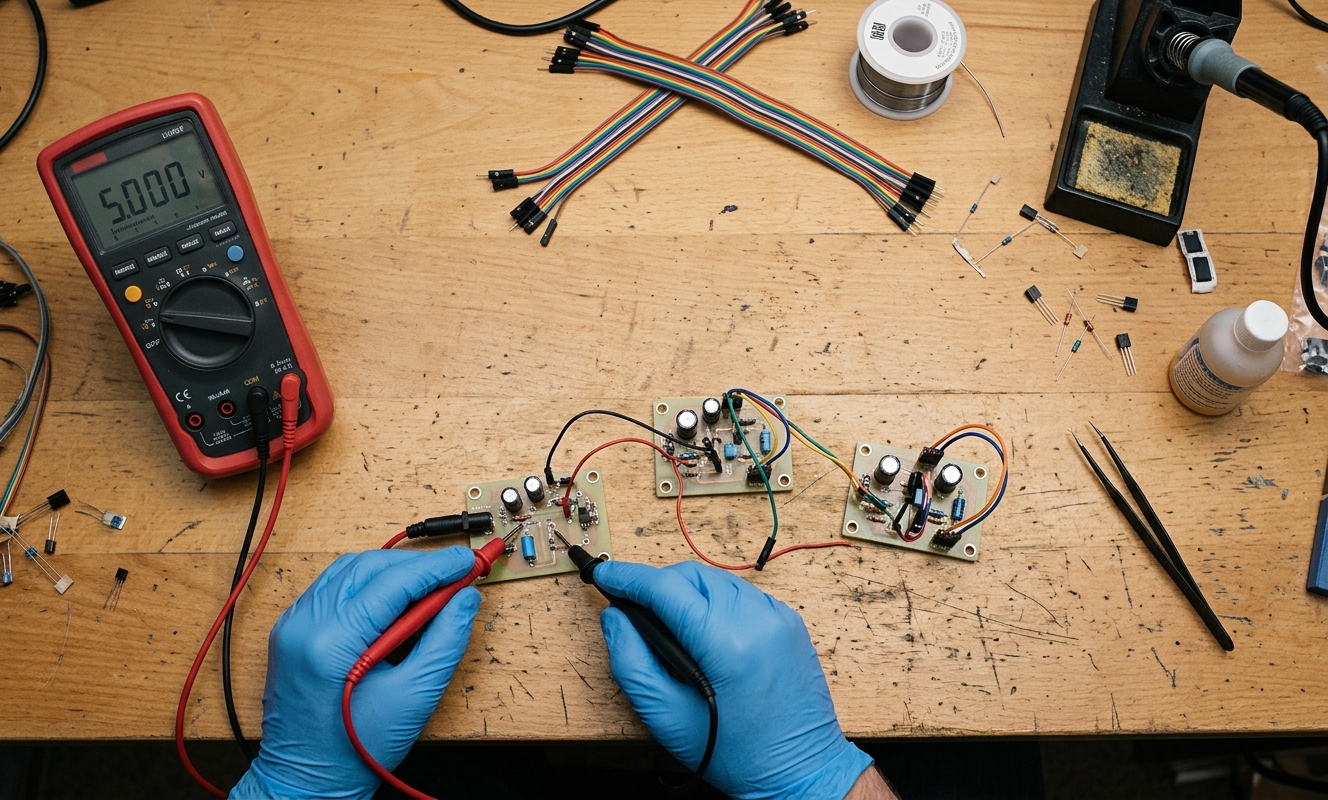
A digital multimeter can find a surprising number of failed electronic components.
It cannot replace a curve tracer or an oscilloscope, but for a damaged MOSFET, open optocoupler LED, or faulty NTC thermistor, a few basic measurements often tell you where to look next.
One important rule comes first:power must be removed before resistance or diode measurements.Large capacitors should also be discharged. Testing a component while it is still connected to a powered circuit can damage the meter and produce misleading results.
Another point I have learned over the years is that a multimeter test is usually ascreening test, not a complete qualification test. A component can pass a static measurement and still fail when voltage, current, temperature, or switching frequency increases.
How to Test a MOSFET With a Multimeter
The first step is identifying theGate (G), Drain (D), and Source (S)from the exact datasheet. Do not assume every SOT-23 or TO-220 MOSFET has the same pin order.
For a basic MOSFET check, diode mode is useful because the body diode is normally visible between Drain and Source.
First, place the probes between D and S in one direction, then reverse them.
For a typical N-channel MOSFET, one direction may show the body-diode forward voltage, while the opposite direction should normally showOLwhen the gate is not charged. A reading close to 0V in both directions is a strong sign of a D-S short.
Next, check the Gate.
Measure G-S and G-D in resistance mode. A healthy MOSFET normally shows very high resistance because the insulated gate should not provide a DC conduction path. A low resistance reading between Gate and Source or Gate and Drain is suspicious.
So, how do youcheck if a MOSFET is blown?
If D-S is shorted both ways, or the Gate appears shorted to another terminal, the device is very likely damaged.
There is one catch: some circuits contain parallel components, so anin-circuit MOSFET testmay not give a clean result. Removing the MOSFET, or lifting one terminal where practical, provides a much more reliable measurement.
Can a Multimeter Prove That a MOSFET Is Good?
Not completely.
A multimeter cannot tell you whether the MOSFET has the correct RDS(on) at the required gate voltage, whether it switches fast enough, or whether it breaks down under high voltage.
For example, a MOSFET can still show a normal body-diode reading after suffering increased leakage or degraded switching performance.
For that reason, I use the multimeter to find obvious failures first. If the result looks normal but the board still has a problem, the next step is normally a live voltage test or a controlled bench test.
How to Test an Optocoupler
An optocoupler is a little different because the input LED and output transistor are electrically isolated.
For a common 4-pin phototransistor optocoupler such as a PC817-type device, the LED side can usually be checked with diode mode.
Place the red probe on the LED anode and the black probe on the cathode. A forward-voltage reading should normally appear. Reverse the probes and the meter should generally showOL.
If both directions show OL, the input LED may be open.
If both directions show an extremely low voltage or near-short condition, the LED may be damaged.
The transistor side is harder to evaluate with a basic meter. You can check for obvious collector-emitter or collector-base shorts, but a normal reading does not prove that the optocoupler has the expected CTR.
This is particularly important withPC817 replacementwork. A part may pass a simple diode check and still have insufficient CTR for the original circuit.
Also remember that a multimeter cannot verify a 3kV, 5kV, or other rated isolation barrier. Isolation voltage is a safety specification that requires the appropriate test equipment and test method.
How to Test an NTC Thermistor With a Multimeter
An NTC thermistor is one of the easier components to test.
Set the meter to resistance mode and measure across the two terminals.
At room temperature, the measured resistance should be reasonably close to the specified R25 value.
For example, a nominal10K NTC thermistorshould be around 10kΩ at 25°C, within its specified tolerance.
But that does not mean every 10K NTC is interchangeable.
AB3950andB3435thermistor can both be 10kΩ at 25°C while having different resistance-temperature curves.
A useful practical test is to warm the thermistor gently and watch the resistance fall. Because it is an NTC, resistance should decrease as temperature rises.
If the resistance remains nearly unchanged, jumps around, or becomes open during gentle heating, the part may be damaged.
For anin-circuit thermistor resistance test, be careful. Other resistors, IC inputs, and parallel paths can affect the meter reading. Disconnecting one side of the thermistor gives a cleaner result.
Common Multimeter Results
|
Component |
Normal Reading |
Possible Fault |
|---|---|---|
|
MOSFET D-S |
Body diode one way;OLthe other way |
Near 0Ω both ways |
|
MOSFET G-S / G-D |
Very high resistance |
Low resistance |
|
Optocoupler LED |
Forward diode reading;OLreversed |
OL both ways or near-short |
|
NTC |
Resistance close to rated value at known temperature |
Open, short, or unstable |
These results are useful for fault finding, but they should always be compared with the component datasheet.
What If the Component Passes but the Circuit Still Fails?
This happens often.
A diode-mode test checks a static junction. It does not reproduce the real operating conditions.
For a MOSFET, you may need to check gate voltage and drain-source voltage under load.
For an optocoupler, CTR and output switching behavior may matter.
For an NTC, the real issue may be the B value, ADC circuit, or firmware lookup table rather than the thermistor itself.
So I would not replace every part that gives an unusual reading without understanding the surrounding circuit.
What Comes After a Failed Test?
Usually, it is a sourcing problem.
Once the failed component is identified, the next step is finding thesame MPN, an approved second source, or a suitable pin-compatible replacement.
That is especially important for production equipment, where a quick repair part may not be suitable for the BOM.
Need a Replacement Component?
Found a damaged MOSFET, optocoupler, or NTC thermistor during testing? Send us theexact MPN, package, required quantity, or BOM. We can help check original parts, pin-compatible alternatives, availability, and sourcing options.